IO-Link is a serial, bi-directional point-to-point connection for signal transmission and power supply under any network, fieldbus, or backplane bus.
IO-Link is the first I/O technology for communicating with sensors and actuators to be adopted as an international standard as described in IEC 61131-9. This technology enables the cyclic exchange of digital input and output process data as well as the acyclic exchange of parameter and diagnostic data between a master and its associated devices. A master is coupled to higher-level systems such as a fieldbus, industrial Ethernet, or even directly to MES, ERP, or cloud-based systems.
Benefits of IO-Link
- The IO-Link system offers decisive benefits as a digital interface for connecting sensors/actuators.
- Open standard according to IEC 61131-9
- Tool-supported parameter assignment and central data management
- Simple, standardized wiring and a significantly reduced variety of interfaces for sensors/actuators
- Consistent communication between sensors/actuators and the controller
- Consistent diagnostic information down to the sensor/actuator level
- Dynamic change of sensor/actuator parameters by the controller or the operator on the HMI
- Automatic parameter reassignment for device replacement during operation
- Integrated device identification
IO-Link Overview
Components
There are five basic elements in an IO-Link installation:
- IO-Link devices
- IO-Link masters
- Unshielded cables
- IODD files
- Engineering tool
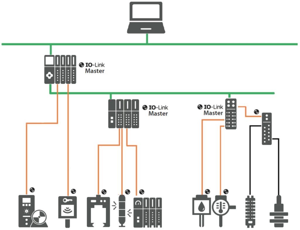
IO-Link device
The communicating field device, such as a sensor, switchgear, valve terminal, RFID device, or signal lamp
IO-Link master
Represents the gateway between an IO-Link device and the higher-level communication system such as a fieldbus or a device-specific backplane

Unshielded standard cable
The standard connection between IO-Link master and device

IODD File
An electronic device description – the IODD file (IO Device Description) – is available for each device. The IODD stores a variety of information for system integration.
IO-Link Configuration Tool
Used for project engineering and parameterization of the IO-Link system and associated devices
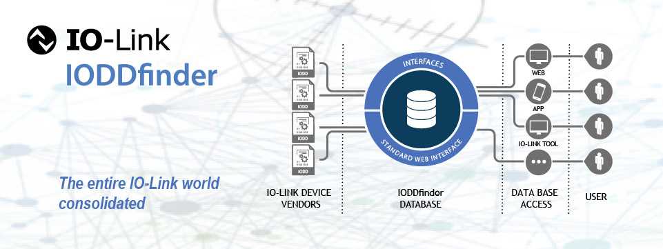
IODDfinder
The IODDfinder is a non-proprietary central IODD database maintained by the IO-Link Community. It makes all IODDs from device manufacturers available for viewing and download.
IO-Link Interface
IP65/67 Connection
For connection in IP65/67 environments, commonly an M12 connector is employed. Sensors usually have a 4-pin plug and actuators a 5-pin plug. IO-Link masters generally have a 5-pin M12 socket.
Port Class A (Type A)
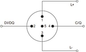
In this type, the functions of pins 2 and 5 are not specified. The manufacturer defines these functions. Pin 2 is usually assigned with an additional digital channel.
Port Class B (Type B)
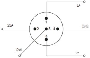
This type provides additional supply voltage and is suitable for the connection of devices that have an increased power demand. In this case, pins 2 and 5 are used to provide additional (galvanically isolated) supply voltage. A 5-conductor standard cable is required in order to use this additional supply voltage.
The device is connected to the master via unshielded 3 or 5-lead standard cables with a length of at most 20 m and cross-section >= 0.34 mm2. Shielding is not necessary. Likewise, no specific guidelines have to be followed when laying the cables.
IO-Link Protocol
Operating Modes
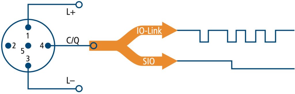
- IO-Link Mode – In “IO-Link” mode, the port is used for IO-Link communication.
- SIO Mode – In “SIO” mode, the port is in standard I/O mode. Depending on the device connected, two possibilities arise:
- DI – The port of the master behaves like a digital input.
- DQ – The port of the master behaves like a digital output.
Transmission Speed
Three transmission rates (baud rates) are specified for IO-Link:
- COM 1 = 4.8 Kbit/s (kbaud)
- COM 2 = 38.4 Kbit/s (kbaud)
- COM 3 = 230.4 Kbit/s (kbaud)
An IO-Link device supports only one of the defined data transmission rates. An IO-Link master supports all data transmission rates and adapts itself automatically to the data transmission rate supported by the device.
Cycle Time
The response time of the IO-Link system provides information about the frequency and speed of the data transmission between the device and master. The response time depends on various factors. The device description file IODD of the device contains a value for the minimum cycle time of the device. This value indicates the time intervals at which the master may address the device. The value has a large influence on the response time. In addition, the master has an internal processing time that is included in the calculation of the response time.
Devices with different minimum cycle times can be configured on one master. The response time differs accordingly for these devices. That is, the response time of the different devices on a master can differ significantly.
When configuring the master, you can specify a fixed cycle time in addition to the device- specific minimum cycle time stored in the IODD. The master then addresses the device based on this specification. The typical response time for a device therefore results from the effective cycle time of the device and the typical internal processing time of the master.
A typical cycle time of 2.3 ms can be achieved at COM-2.
Transmission Quality
IO-Link is a very robust communication system. This communication system operates with a 24 V level. If transmissions fail, the frame is repeated two more times. Only after the failure of the second retry does the IO-Link master recognize a communication failure and signal this to the higher-level controller.
Data Types
Four basic types of data are available:
- Process data –> Cyclic
- Value status –> Cyclic
- Device data –> Acyclic
- Events –> Acyclic
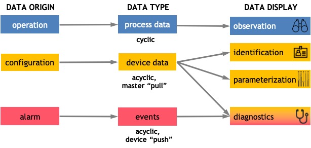
Process Data
The process data of the devices are transmitted cyclically in a data frame in which the size of the process data is specified by the device. Depending on the device, 0 to 32 bytes of process data are possible (for each input and output).
Value Status
Each port has a value status (PortQualifier). The value status indicates whether the process data are valid or invalid. The value status is transmitted cyclically with the process data.
Device Data
Device data can be parameters, identification data, or diagnostic information. They are exchanged acyclically and at the request of the IO-Link master. Device data can be written to the device and also read from the device.
Events
When an event occurs, the device signals the presence of the event to the master. The master then reads out the event. Events can be error messages (e.g. short-circuit) or warnings/ maintenance data (e.g. soiling, overheating). Device error messages are transmitted via the IO-Link master, which can also transmit events on its behalf (e.g wire breaks).
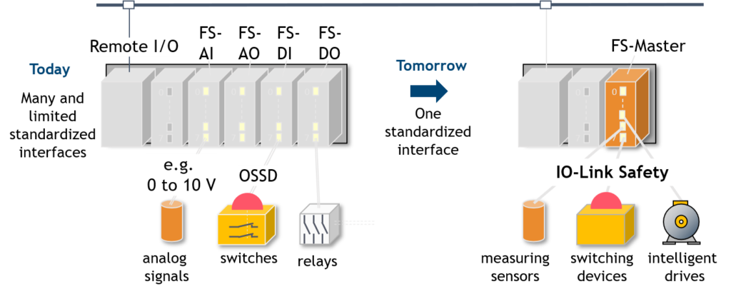
IO-Link Safety
IO-Link Safety is an extension to IO-Link by using an additional safety communication layer on top of both the master and the device sides, thus becoming a functional safety (FS) master and an FS-Device. IO-Link safety has been approved by TÜV-SÜD.
IO-Link Safety can support any type of FS-Device, such as a sensor, actuator, or complex mechatronic. It also allows for new kinds of safety applications, for example, through local safety logic within the FS-Master in conjunction with higher-level safety functions.
Within the system, safety and non-safety data transmission coexist. The point-to-point communication nature of IO-Link Safety eases the user experience in terms of installation and configuration.
Key Benefits
- No special ASICs required
- Lower costs and smaller dimensions
- Robust digital communication
- Gateways to all fieldbuses
- Uniform engineering of devices
FSCP = Functional Safety Communication Protocol
Black Channel Principle
A functional safety communication protocol (FSCP) like PROFIsafe follows the “Black Channel” principle. PROFIsafe is used as a carrier for particular types of messages containing safety process data and additional safety codes.
The IO-Link safety communication layer is located on top of the FS-Device and FS-Master stack.
IO-Link wireless
IO-Link Wireless defines wireless network communication between sensors, actuators, and controllers (PLC) in automation environments. It is designed to provide a similar level of performance and backward compatible interface as a cable connection, ensuring a seamless migration from wired to wireless systems.
Multiple devices can communicate with an IO-Link Wireless master at the same time. With IO-Link Wireless, all data can be transferred from devices: process data, parameters, and diagnostic data.
Specifications
- 2.4 GHz ISM band
- 5 ms cycle time for process data
- Up to 120 wireless devices
- Range of up to 20 meters
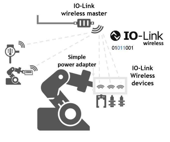
Use Cases
Use cases for the IO-Link Wireless can be found in different applications. This new technology contributes to the general effort to reduce wiring and cabling. Also, it lowers the cabling requirements in harsh environments and as a result, minimizes the number of possible errors. Besides, IO-Link Wireless can simplify the installation of components that are difficult to access in the application.
Robot Arm:
Cable Strain

Conveyor Belt:
Reduction of Cabling
Hygienic Area:
Reduction of Contamination

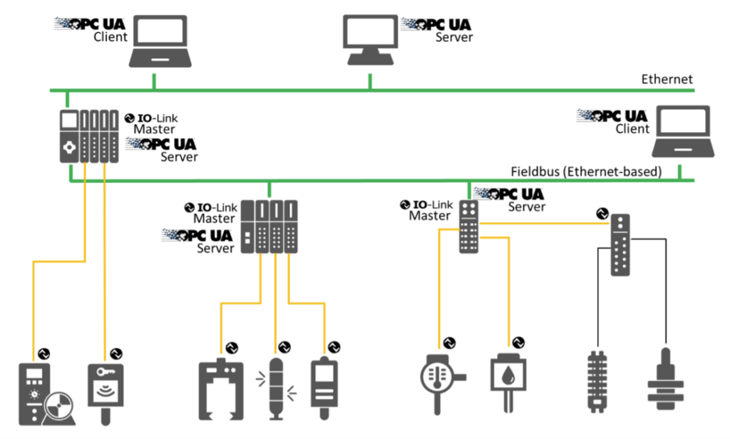
OPC UA for IO-link
For IO-Link, a fieldbus-independent integration via OPC UA can be used to further expand the breadth of possible automation solutions: IO-Link masters, which bundle the data from sensors and actuators, can process these data not only as fieldbus nodes but can also make higher levels available inside and outside of the automation pyramid via OPC UA.
IO-Link to OPC UA Companion Specification
The IO-Link Community developed a method for implementing an integration of IO-Link in OPC UA.
Sensor data can be integrated with little effort and seamlessly in MES and ERP systems, which is often referred to as “sensor-to-cloud” functionality. For many applications, this opening to OPC UA means new flexibility for the use of sensors and actuators.
USE-Cases
- Monitoring process data
- Recording diagnostics
- Reading/writing device parameters
- Configuring masters and devices
- Parameter interpretation via IODD